OpenGL (Open Graphics Library) is a cross-platform graphics API used to communicate with the GPU for rendering 2D and 3D graphics. It provides a programmable rendering pipeline where developers can send geometry, textures, and shader programs to the graphics hardware to generate real-time visual output.
OpenGL itself does not create windows or handle GUI elements. Instead, it focuses on GPU rendering operations such as:
- Drawing geometry
- Executing shaders
- Managing buffers and textures
- Lighting and transformations
- Depth testing and blending
Modern OpenGL uses programmable shaders written in GLSL, allowing full control over how vertices and pixels are processed on the GPU.
It is widely used for:
- 3D graphics
- Visualization
- Shader programming
- Engineering applications
- Interactive rendering systems
Combined with GUI frameworks and modern OpenGL techniques, PyOpenGL can be used to create professional desktop graphics applications.
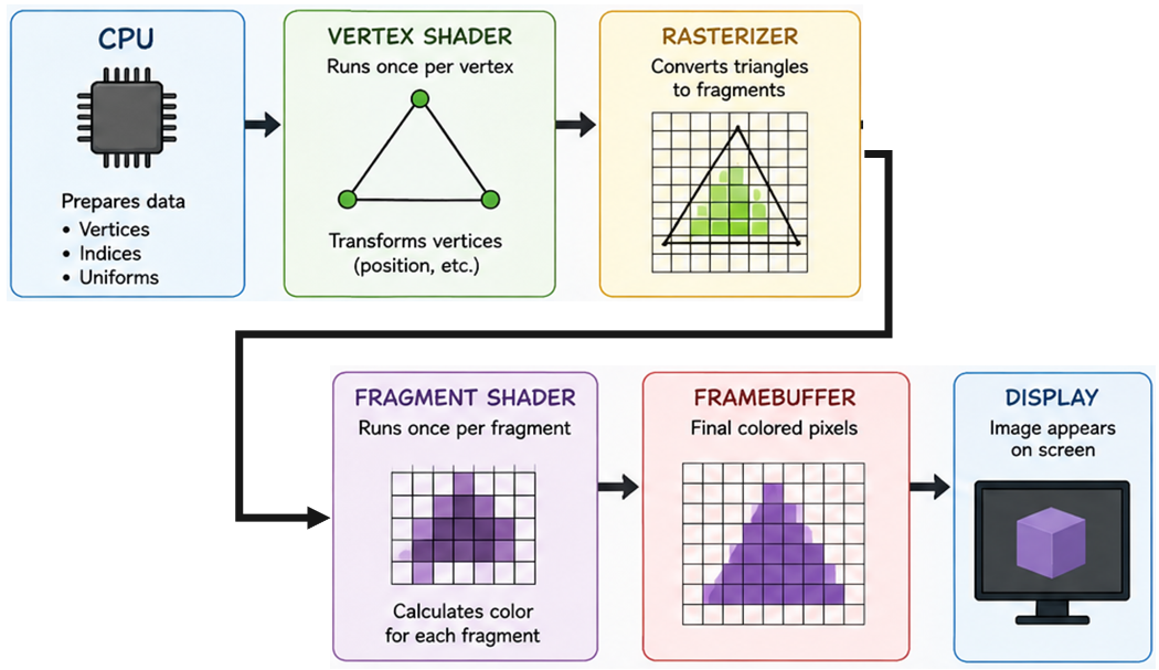
The OpenGL rendering pipeline is the sequence of stages that transforms raw geometric data into pixels displayed on the screen.
It is executed primarily on the GPU and consists of multiple programmable and fixed-function stages. Each stage performs a specific operation on the data before passing it to the next stage.
Vertices
The rendering process begins with vertex data.
Vertices define the geometry of objects and are typically stored inside GPU buffers.
A vertex may contain:
Position
Normal
Color
Texture coordinates
Example:
vertices = [
    -1.0, -1.0, 0.0,
     1.0, -1.0, 0.0,
     0.0,  1.0, 0.0
]
This data is uploaded to the GPU using buffer objects.
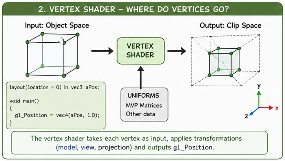
Vertex Shader
The vertex shader is the first programmable stage of the pipeline. It processes each vertex independently and is mainly responsible for:
- Transformations
- Coordinate conversion
- Passing data to later stages
Typical operations include:
- Model transformation
- Camera transformation
- Projection transformation
Example:
gl_Position =
    projection *
    view *
    model *
    vec4(position, 1.0);
The output of the vertex shader is the transformed vertex position in clip space.
Primitive Assembly
OpenGL groups vertices into primitives.
Examples:
- 3 vertices → triangle
- 2 vertices → line
- 1 vertex → point
This stage determines how the GPU interprets vertex data.
Clipping
Geometry outside the visible viewing volume is discarded.
OpenGL clips geometry against:
- Near plane
- Far plane
- Left plane
- Right plane
- Top plane
- Bottom plane
Only visible geometry continues through the pipeline.
Rasterization
Rasterization converts geometric primitives into fragments.
A fragment represents a potential pixel on the screen.
During rasterization:
=> Triangles are converted into fragments
=> Vertex attributes are
interpolated
Interpolated values may include:
- Colors
- Normals
- Texture coordinates
Fragment Shader
The fragment shader processes each fragment generated during rasterization.
It determines the final appearance of pixels.
Typical operations:
- Lighting calculations
- Texture sampling
- Color generation
- Transparency effects
Example:
FragColor = vec4(finalColor, 1.0);
The output of the fragment shader is the final color of the pixel.
The fragment shader is one of the most important stages for visual quality.
Framebuffer
The framebuffer stores the final rendered image before it is displayed.
It typically contains:
- Color buffer
- Depth buffer
- Stencil buffer
After rendering is complete, the framebuffer image appears on the screen.
QOpenGLWidget allows OpenGL rendering to be integrated directly into desktop GUI applications. It manages the OpenGL context, rendering lifecycle and framebuffer automatically.
OpenGL Context
Automatically creates and manages the OpenGL rendering context.
GPU Rendering
Provides hardware accelerated rendering inside Qt applications.
GUI Integration
Works seamlessly with layouts, menus, toolbars and dock widgets.
Basic QOpenGLWidget Class
from PySide6.QtOpenGLWidgets import QOpenGLWidget

class GLWidget(QOpenGLWidget):

    def initializeGL(self):
        pass

    def resizeGL(self, w, h):
        pass

    def paintGL(self):
        pass
Important Functions
initializeGL()
Called once when the OpenGL context is created. Used to initialize shaders, buffers and textures.
resizeGL()
Called whenever the widget is resized. Used to update the viewport and projection matrix.
paintGL()
Called every frame to execute the rendering pipeline.
Rendering Lifecycle
Application Starts
        ↓
QOpenGLWidget Created
        ↓
initializeGL()
        ↓
resizeGL()
        ↓
paintGL()
        ↓
Screen Updated
        ↓
paintGL() Repeats
Updating the Viewport
def resizeGL(self, w, h):

    glViewport(0, 0, w, h)
The viewport defines the rendering area inside the widget.
Clearing the Screen
def paintGL(self):

    glClearColor(0.2, 0.2, 0.2, 1.0)

    glClear(
        GL_COLOR_BUFFER_BIT |
        GL_DEPTH_BUFFER_BIT
    )
The framebuffer is cleared before rendering a new frame.
Updating the Widget
self.update()
Calling update() schedules a repaint and triggers the paintGL() function.
Mouse and Keyboard Events
def mousePressEvent(self, event):
    pass

def mouseMoveEvent(self, event):
    pass

def wheelEvent(self, event):
    pass
QOpenGLWidget supports all standard Qt input events for implementing camera movement and interaction.
Advantages of QOpenGLWidget
Easy Integration
Integrates directly into Qt layouts and widgets.
Cross Platform
Works on Windows, Linux and macOS.
Hardware Accelerated
Uses GPU accelerated rendering through OpenGL.
Event System
Full support for Qt mouse and keyboard events.
QOpenGLWidget Rendering Flow
Qt Application
        ↓
QOpenGLWidget
        ↓
OpenGL Context
        ↓
GPU Rendering
        ↓
Framebuffer
        ↓
Widget Display
import sys # access command line arguments for QApplication
from PySide6.QtWidgets import QApplication # Qt application management
from PySide6.QtOpenGLWidgets import QOpenGLWidget # widget for OpenGL rendering
from OpenGL.GL import * # import OpenGL functions and constants
class GLWidget(QOpenGLWidget):
# custom OpenGL widget subclass
def initializeGL(self):
# called once when the GL context is first created
# set the clear color for the window background
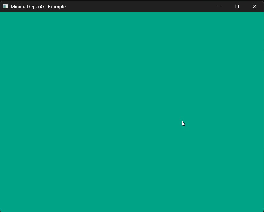
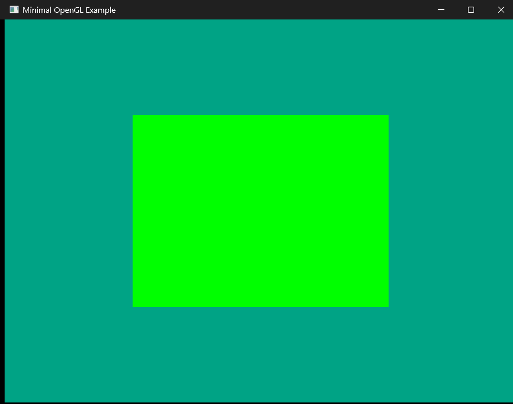
glClearColor(0, 0.64, 0.52, 1.0)
def paintGL(self):
# called whenever the widget needs to be redrawn
# clear the color buffer using the previously set clear color
glClear(GL_COLOR_BUFFER_BIT)
app = QApplication(sys.argv) # create the Qt application with command line args
window = GLWidget() # create an instance of the OpenGL widget
window.setWindowTitle("Minimal OpenGL Example") # set the window title
window.resize(800, 600) # set the initial window size
window.show() # show the window on screen
sys.exit(app.exec()) # enter the Qt event loop and exit cleanly when done
This code creates a simple OpenGL window with a teal background using PySide6 and QOpenGLWidget.
Shaders allow developers to customize how vertices and pixels are processed, enabling advanced visual effects and real-time rendering techniques.
There are several types of shaders, including:
- Vertex Shader
- Fragment Shader
- Geometry Shader
- Tessellation Shader
- Compute Shader
Responsibilities of a Vertex Shader
Transformations
Converts vertices between coordinate spaces.
Data Processing
Processes vertex attributes such as normals and colors.
Attribute Passing
Sends interpolated data to the fragment shader.
Position Output
Outputs the final clip-space vertex position.
Basic Vertex Shader
#version 330 core

layout(location = 0) in vec3 position;

void main()
{
    gl_Position = vec4(position, 1.0);
}
Code Explanation
#version 330 core
Specifies the GLSL shader language version.
layout(location = 0)
Defines the vertex attribute location used by OpenGL.
in vec3 position
Receives the vertex position from the vertex buffer.
gl_Position
Built-in output variable containing the final vertex position.
Vertex Transformations
In most applications, vertices are transformed using model, view and projection matrices.
Local Space
        ↓
World Space
        ↓
View Space
        ↓
Clip Space
Vertex Shader with Transformations
#version 330 core

layout(location = 0) in vec3 position;

uniform mat4 model;
uniform mat4 view;
uniform mat4 projection;

void main()
{
    gl_Position =
        projection *
        view *
        model *
        vec4(position, 1.0);
}
Uniform Variables
model
Positions the object in world space.
view
Represents the camera transformation.
projection
Converts 3D coordinates into clip space.
Vertex Shader Data Flow
Vertex Buffer
        ↓
Vertex Shader
        ↓
Transformed Vertices
        ↓
Rasterization
        ↓
Fragment Shader
Important Notes
- Vertex shaders execute once per vertex.
- The output position must be written to gl_Position.
- Vertex shaders cannot create pixels directly.
- The vertex shader runs on the GPU.
- Vertex shaders are written using GLSL.
The fragment shader runs after rasterization and is executed once for every fragment generated from a primitive. Its primary responsibility is determining the final appearance of pixels on the screen.
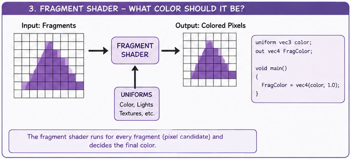
Responsibilities of a Fragment Shader
Color Output
Calculates the final color of fragments.
Lighting
Performs lighting and shading calculations.
Texturing
Samples textures and applies surface detail.
Visual Effects
Handles transparency, contours and post-processing effects.
Basic Fragment Shader
#version 330 core

out vec4 FragColor;

void main()
{
    FragColor = vec4(1.0, 0.0, 0.0, 1.0);
}
Code Explanation
#version 330 core
Specifies the GLSL shader language version.
out vec4 FragColor
Output variable storing the final fragment color.
vec4(...)
Represents RGBA color values using four floating point components.
Alpha Value
The fourth component controls fragment transparency.
RGBA Color Components
vec4(red, green, blue, alpha)

Example:

vec4(1.0, 0.0, 0.0, 1.0)

Red   = 1.0
Green = 0.0
Blue  = 0.0
Alpha = 1.0
Receiving Data from the Vertex Shader
Fragment shaders can receive interpolated data from the vertex shader.
#version 330 core

in vec3 vertexColor;

out vec4 FragColor;

void main()
{
    FragColor = vec4(vertexColor, 1.0);
}
Attribute Interpolation
Values passed from the vertex shader are automatically interpolated across the surface of a primitive during rasterization.
Vertex Shader Outputs
        ↓
Rasterization
        ↓
Interpolated Fragment Data
        ↓
Fragment Shader
Fragment Shader Lighting Example
vec3 finalColor = baseColor;

float diffuse =
    max(dot(normal, lightDir), 0.0);

finalColor *= diffuse;

FragColor = vec4(finalColor, 1.0);
Lighting calculations are commonly performed inside the fragment shader to achieve smooth shading and realistic visual appearance.
Texture Sampling
uniform sampler2D textureSampler;

in vec2 texCoord;

FragColor =
    texture(textureSampler, texCoord);
Fragment shaders can sample textures using UV coordinates.
Fragment Shader Data Flow
Vertex Shader
        ↓
Rasterization
        ↓
Fragment Shader
        ↓
Depth Testing
        ↓
Framebuffer
Important Notes
- Fragment shaders execute once per fragment.
- Fragment shaders determine the final pixel color.
- Fragment shaders run on the GPU.
- Fragment shaders are written using GLSL.
- Fragment shaders are commonly used for lighting and texturing.
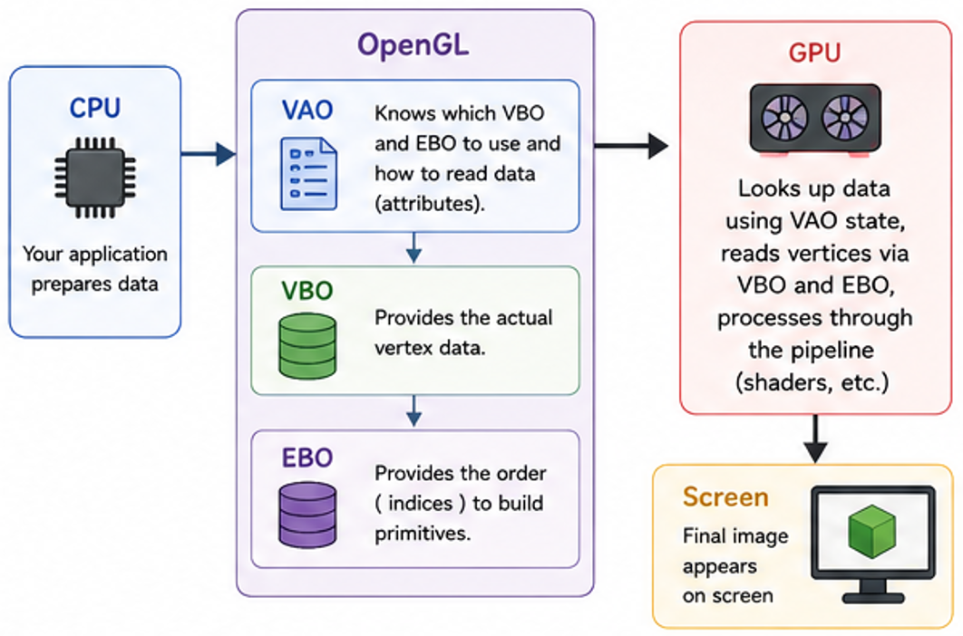
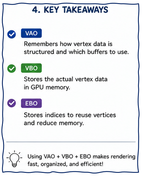
Modern OpenGL stores rendering data inside GPU memory using buffer objects. Buffers improve rendering performance by allowing geometry data to remain on the GPU instead of sending it every frame from the CPU.
Why Buffers are Required
Without buffers, geometry data would need to be sent repeatedly from the CPU to the GPU during rendering.
Main Buffer Types
VBO
Stores vertex data such as positions, normals and texture coordinates.
EBO
Stores indices used for indexed rendering.
VAO
Stores vertex attribute configuration and buffer bindings.
Vertex Buffer Object (VBO)
A VBO stores vertex data inside GPU memory.
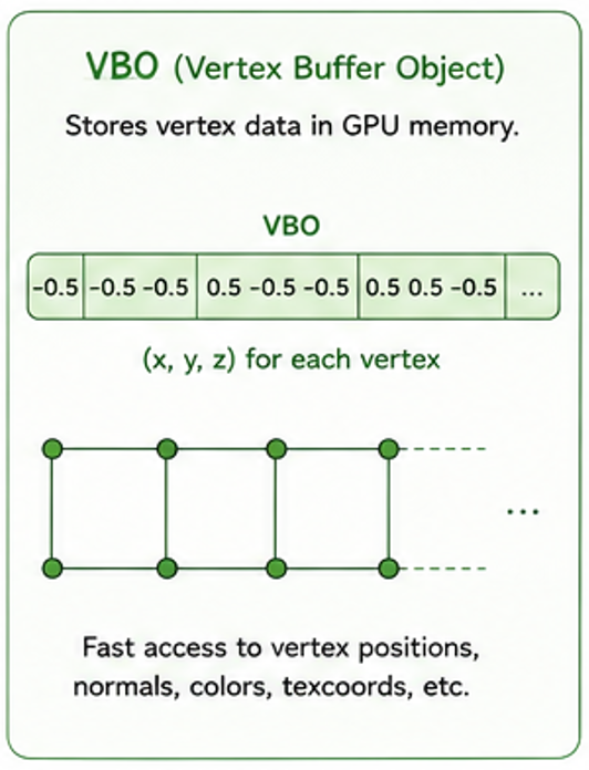
vertices = np.array([
    -0.5, -0.5, 0.0,
     0.5, -0.5, 0.0,
     0.0,  0.5, 0.0
], dtype=np.float32)
This array contains vertex positions for a triangle.
Creating a VBO
vbo = glGenBuffers(1)

glBindBuffer(GL_ARRAY_BUFFER, vbo)

glBufferData(
    GL_ARRAY_BUFFER,
    vertices.nbytes,
    vertices,
    GL_STATIC_DRAW
)
VBO Explanation
glGenBuffers()
Creates a new OpenGL buffer object.
glBindBuffer()
Binds the buffer to a target type.
GL_ARRAY_BUFFER
Specifies that the buffer stores vertex data.
glBufferData()
Uploads data from CPU memory to GPU memory.
Element Buffer Object (EBO)
An EBO stores indices that define how vertices form primitives.
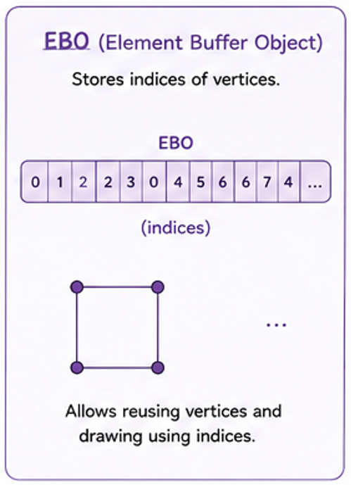
indices = np.array([
    0, 1, 2,
    2, 3, 0
], dtype=np.uint32)
These indices define two triangles forming a quad.
Creating an EBO
ebo = glGenBuffers(1)

glBindBuffer(
    GL_ELEMENT_ARRAY_BUFFER,
    ebo
)

glBufferData(
    GL_ELEMENT_ARRAY_BUFFER,
    indices.nbytes,
    indices,
    GL_STATIC_DRAW
)
Why EBOs are Important
Without EBO
        ↓
Duplicate Vertices
        ↓
More GPU Memory

With EBO
        ↓
Reuse Vertices
        ↓
Efficient Rendering
Indexed rendering reduces duplicate geometry data and improves rendering efficiency.
Vertex Array Object (VAO)
A VAO stores vertex attribute configuration and buffer state.
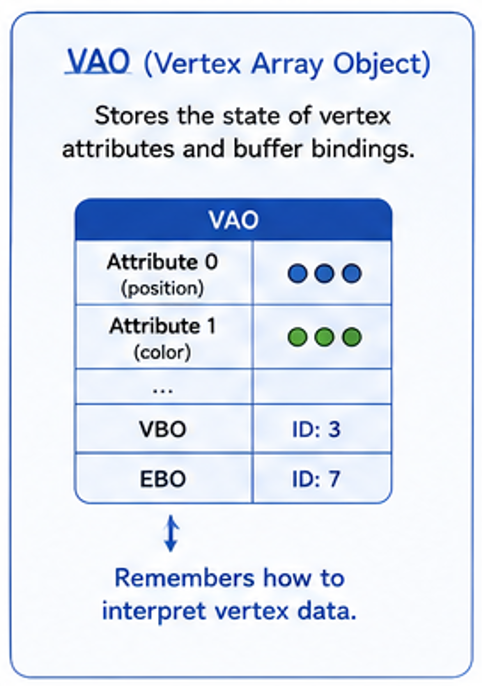
VAO Stores:
    • Vertex Attribute Layout
    • Bound VBO
    • Bound EBO
    • Attribute Configuration
Creating a VAO
vao = glGenVertexArrays(1)

glBindVertexArray(vao)
Vertex Attribute Configuration
glVertexAttribPointer(
    0,
    3,
    GL_FLOAT,
    GL_FALSE,
    3 * 4,
    ctypes.c_void_p(0)
)

glEnableVertexAttribArray(0)
glVertexAttribPointer Parameters
| Parameter | Description |
|---|---|
| 0 | Vertex attribute location |
| 3 | Number of components (vec3) |
| GL_FLOAT | Data type |
| GL_FALSE | No normalization |
| 3 * 4 | Vertex stride in bytes |
| Offset | Starting memory offset |
Complete Rendering Flow
Vertex Data
        ↓
VBO
        ↓
EBO
        ↓
VAO Configuration
        ↓
glDrawElements()
        ↓
Vertex Shader
        ↓
Fragment Shader
        ↓
Framebuffer
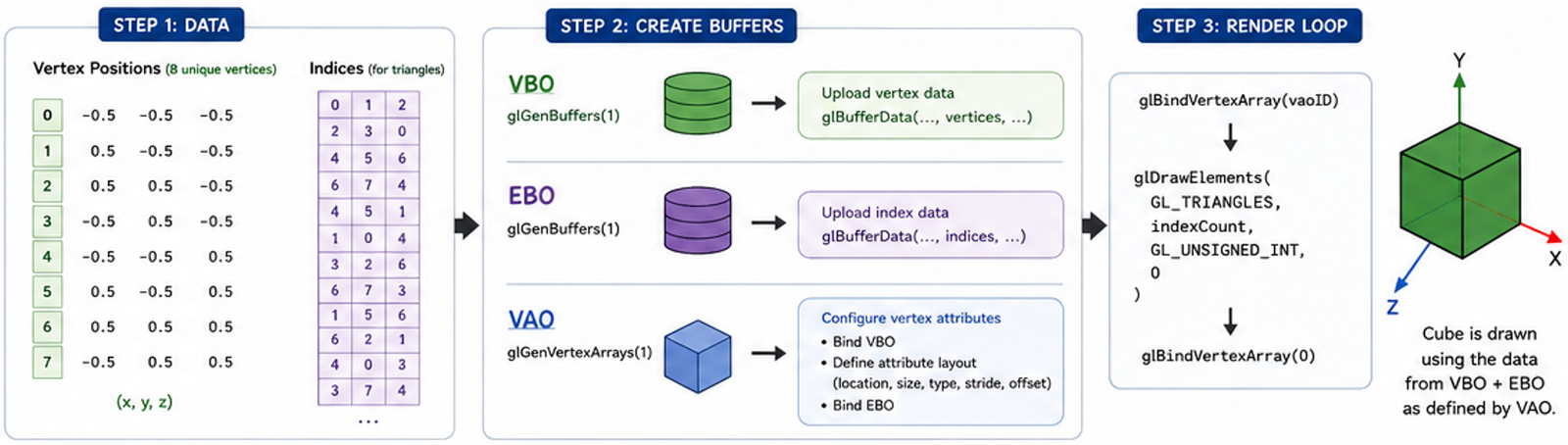
Rendering Geometry
glBindVertexArray(vao)

glDrawElements(
    GL_TRIANGLES,
    len(indices),
    GL_UNSIGNED_INT,
    None
)
Once the VAO is configured, rendering becomes very simple.
VAO vs VBO vs EBO
| Object | Purpose |
|---|---|
| VBO | Stores vertex data |
| EBO | Stores triangle indices |
| VAO | Stores vertex layout configuration |
Important Notes
- Buffers store data inside GPU memory.
- VBOs store vertex attributes.
- EBOs store indexed connectivity.
- VAOs store vertex attribute configuration.
- Modern OpenGL rendering heavily relies on buffer objects.
OpenGL does not automatically know how vertices should form geometry. Primitive types specify whether vertices represent points, lines or triangles.
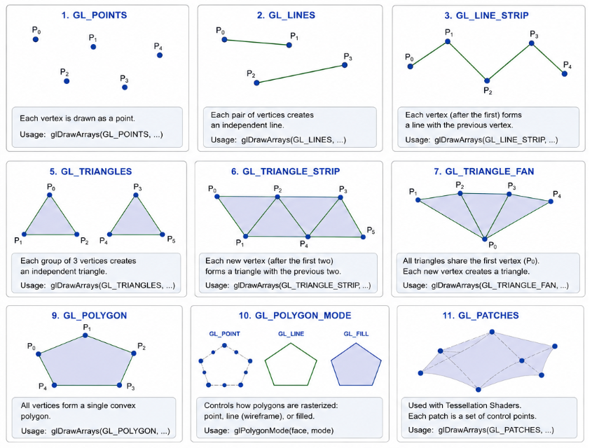
We will extend our minimal opengl window to draw a cube using these primitives.
# =========================================================
# Vertex Shader
# =========================================================
vertex_shader_source = """
#version 330 core

layout(location = 0) in vec3 aPos;

void main()
{
    gl_Position = vec4(aPos, 1.0);
}
"""

# =========================================================
# Fragment Shader
# =========================================================
fragment_shader_source = """
#version 330 core

uniform vec3 color;
out vec4 FragColor;

void main()
{
    FragColor = vec4(color, 1.0);
}
"""
The vertex shader receives vertex positions from the vertex buffer
and outputs the final clip-space position using gl_Position.
The fragment shader calculates the final pixel color.
The cube color is controlled using a uniform variable.
# Compile vertex shader
vertex_shader = glCreateShader(GL_VERTEX_SHADER)
glShaderSource(vertex_shader, vertex_shader_source)
glCompileShader(vertex_shader)

# Check for compilation errors
if not glGetShaderiv(vertex_shader, GL_COMPILE_STATUS):
    error = glGetShaderInfoLog(vertex_shader).decode()
    print(f"Vertex shader compilation failed:\n{error}")
    return None
OpenGL shaders must be: created, compiled, and linked into a shader program before rendering.
# Link shaders into a program
self.shader_program = glCreateProgram()
glAttachShader(self.shader_program, vertex_shader)
glAttachShader(self.shader_program, fragment_shader)
glLinkProgram(self.shader_program)

# Check for linking errors
if not glGetProgramiv(self.shader_program, GL_LINK_STATUS):
    error = glGetProgramInfoLog(self.shader_program).decode()
    print(f"Shader program linking failed:\n{error}")
    return None

# Clean up shaders as they are no longer needed after linking
glDeleteShader(vertex_shader)
glDeleteShader(fragment_shader)
The vertex and fragment shaders are linked together into a shader program.
    # =========================================================
    # Cube Geometry
    # =========================================================
    def CreateCube(self):
        # This function would create vertex buffers and
        # set up vertex attributes for a cube

        vertices = np.array([
            # front
            -0.5, -0.5,  0.5,
            0.5, -0.5,  0.5,
            0.5,  0.5,  0.5,
            -0.5,  0.5,  0.5,

            # back
            -0.5, -0.5, -0.5,
            0.5, -0.5, -0.5,
            0.5,  0.5, -0.5,
            -0.5,  0.5, -0.5,
        ], dtype=np.float32)

        indices = np.array([
            0, 1, 2, 2, 3, 0,   # front
            1, 5, 6, 6, 2, 1,   # right
            5, 4, 7, 7, 6, 5,   # back
            4, 0, 3, 3, 7, 4,   # left
            3, 2, 6, 6, 7, 3,   # top
            4, 5, 1, 1, 0, 4    # bottom
        ], dtype=np.uint32)

        return vertices, indices
The cube is defined using vertex positions stored in a NumPy array.
Indices define how vertices form triangles.
Indexed rendering avoids duplicate vertex data.
    # =========================================================
    # VAO / VBO / EBO
    # =========================================================
    def SetupBuffers(self):

        self.vertices, self.indices = self.CreateCube()  # get cube geometry data

        # create one Vertex Array Object, one Vertex Buffer Object, and one Element Buffer Object
        self.vao = glGenVertexArrays(1)
        self.vbo = glGenBuffers(1)
        self.ebo = glGenBuffers(1)

        # bind the VAO so the following vertex state is stored in it
        glBindVertexArray(self.vao)

        # bind and upload vertex data to the VBO
        glBindBuffer(GL_ARRAY_BUFFER, self.vbo)
        glBufferData(GL_ARRAY_BUFFER, self.vertices.nbytes, self.vertices, GL_STATIC_DRAW)

        # bind and upload index data to the EBO
        glBindBuffer(GL_ELEMENT_ARRAY_BUFFER, self.ebo)
        glBufferData(GL_ELEMENT_ARRAY_BUFFER, self.indices.nbytes, self.indices, GL_STATIC_DRAW)

        # define the layout of the vertex data:
        # location = 0, 3 floats per vertex, no normalization,
        # stride = 3 * 4 bytes, offset = 0
        glVertexAttribPointer(
            0,                  # location
            3,                  # vec3
            GL_FLOAT,
            GL_FALSE,
            3 * 4,              # stride in bytes
            ctypes.c_void_p(0)  # offset in the buffer
        )
        glEnableVertexAttribArray(0)  # enable the position attribute

        # unbind the VAO to avoid accidental state changes
        glBindVertexArray(0)
Geometry data is uploaded from CPU memory into GPU memory.
    def initializeGL(self):
        # called once when the GL context is first created
        # set the clear color for the window background
        glClearColor(0, 0.64, 0.52, 1.0)

        self.CreateShaderProgram()  # compile and link the shader program
        self.SetupBuffers()  # set up vertex buffers for the cube geometry
def paintGL(self):
        # called whenever the widget needs to be redrawn
        # clear the color buffer using the previously set clear color
        glClear(GL_COLOR_BUFFER_BIT)

        self.draw()  # call the draw function to render the cube geometry
def draw(self):
        # This function would bind the shader program,
        # set uniforms, bind the VAO, and issue the draw call
        glUseProgram(self.shader_program)

        # set uniform color
        color_loc = glGetUniformLocation(self.shader_program, "color")
        glUniform3f(color_loc, 0.0, 1.0, 0.0)

        glBindVertexArray(self.vao)
        glDrawElements(GL_TRIANGLES,
                        len(self.indices), GL_UNSIGNED_INT, None)
        glBindVertexArray(0)  # unbind the VAO after drawing
This function is called whenever the widget needs to be redrawn. The framebuffer is cleared before rendering the cube.
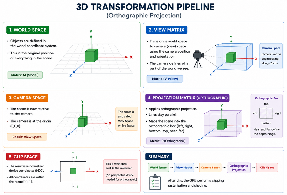
In OpenGL, projection matrices define how a 3D scene is viewed by the camera. The two most common projection types are orthographic projection and perspective projection.
Projection Types
Orthographic Projection
Objects remain the same size regardless of distance from the camera.
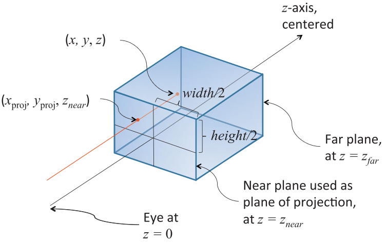
Perspective Projection
Objects appear smaller as their distance from the camera increases.
Orthographic Projection
Orthographic projection removes perspective distortion and preserves object dimensions regardless of depth.
Parallel Projection Rays
        ↓
No Perspective Distortion
        ↓
Constant Object Size
Orthographic projection is commonly used in: CAD software, engineering tools, architectural applications and technical visualization.
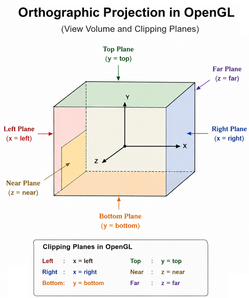
Orthographic Projection Matrix
projection = ortho(left,right,bottom,top,near,far)
The orthographic matrix defines a rectangular viewing volume.
Orthographic Parameters
Left / Right
Horizontal boundaries of the viewing volume.
Bottom / Top
Vertical boundaries of the viewing volume.
Near / Far
Depth range of visible geometry.
Camera System
The camera defines how the scene is viewed. In OpenGL, the camera is implemented using the view matrix.
View Matrix
The view matrix transforms the scene relative to the camera position and orientation.
view = lookAt(
    cameraPosition,
    targetPosition,
    upDirection
)
Camera Parameters
Position
Defines the location of the camera in 3D space.
Target
Defines the point the camera is looking at.
Up Vector
Defines the vertical orientation of the camera.
Camera Movement
Interactive applications commonly support: orbiting, panning and zooming.
Orbit
Rotate the camera around the scene.
Pan
Move the camera horizontally and vertically.
Zoom
Move the camera closer or farther from the scene.
Complete Transformation Pipeline
gl_Position =
    projection *
    view *
    model *
    vec4(position, 1.0);
Vertices are transformed from local coordinates into clip space before rasterization.
Coordinate Transformation Flow
Local Space
        ↓
Model Matrix
        ↓
World Space
        ↓
View Matrix
        ↓
Camera Space
        ↓
Projection Matrix
        ↓
Clip Space
        ↓
Screen Space
Important Notes
- Orthographic projection preserves object dimensions.
- Perspective projection creates realistic depth perception.
- The camera is implemented using the view matrix.
- Projection matrices convert 3D coordinates into clip space.
- The final transformed vertex position is written to gl_Position.
In OpenGL, ray casting can be implemented by generating a ray from the camera through the mouse position and testing for intersections with scene geometry.
Ray Casting Flow
Mouse Position
        ↓
Normalized Device Coordinates
        ↓
View Space Ray
        ↓
World Space Ray
        ↓
Intersection Tests
        ↓
Selected Object
Ray Intersection Testing
Once the ray is generated, intersection tests are performed against geometry.
Ray vs Sphere
Simple and fast collision testing.
Ray vs Box
Commonly used for bounding volume testing.
Ray vs Triangle
Used for precise mesh and surface selection.
Ray-Triangle Intersection
Most 3D geometry is composed of triangles, so ray-triangle intersection is one of the most important selection algorithms in computer graphics.
Ray
        ↓
Triangle Intersection Test
        ↓
Hit Position
        ↓
Closest Intersection
        ↓
Selected Object
Importance of Ray Casting
Object Selection
Select objects directly using the mouse cursor.
Face Picking
Select individual mesh faces and surfaces.
Measurements
Measure distances and geometry locations.
Interaction
Enable interactive manipulation of 3D scenes.
Important Notes
- Ray casting converts 2D mouse input into a 3D selection ray.
- Ray intersection testing is heavily based on vector mathematics.
- Most object selection systems rely on ray-triangle intersection.
- Accurate picking requires inverse projection and view transformations.
- Ray casting is widely used in CAD, games and scientific visualization applications.
    def mousePressEvent(self, e):
        self.last_pos = e.position().toPoint()
        self.buttons = e.buttons()

    def mouseMoveEvent(self, e):
        curr = e.position().toPoint()

        dx = curr.x() - self.last_pos.x()
        dy = curr.y() - self.last_pos.y()

        if self.buttons & Qt.LeftButton:
            p1 = self._map_to_ndc(self.last_pos)
            p2 = self._map_to_ndc(curr)
            self.camera.rotate(p1, p2)

        elif self.buttons & Qt.MiddleButton:
            self.camera.pan(dx, dy)

        self.last_pos = curr
        self.update()

    def _map_to_ndc(self, pos):
        w, h = self.width(), self.height()
        x = (2.0 * pos.x() - w) / w
        y = (h - 2.0 * pos.y()) / h
        return (x, y)
Throughout this discussion, we explored the complete rendering pipeline: OpenGL fundamentals, shaders, GPU buffers, camera systems, projection matrices, indexed rendering, object selection and interactive rendering techniques. These concepts form the foundation of IGLGraphics Library.
What We Built
PySide6 Application
        ↓
QOpenGLWidget
        ↓
PyOpenGL
        ↓
Modern OpenGL Pipeline
        ↓
Shaders
        ↓
GPU Buffers
        ↓
Interactive 3D Rendering
Instead of building isolated rendering demos, the goal was to gradually develop a complete real-time visualization system.
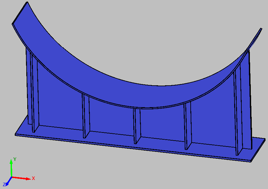
IGLViewer combines PySide6, PyOpenGL and the modern OpenGL rendering pipeline to create an interactive engineering visualization environment for CAD and mesh data.
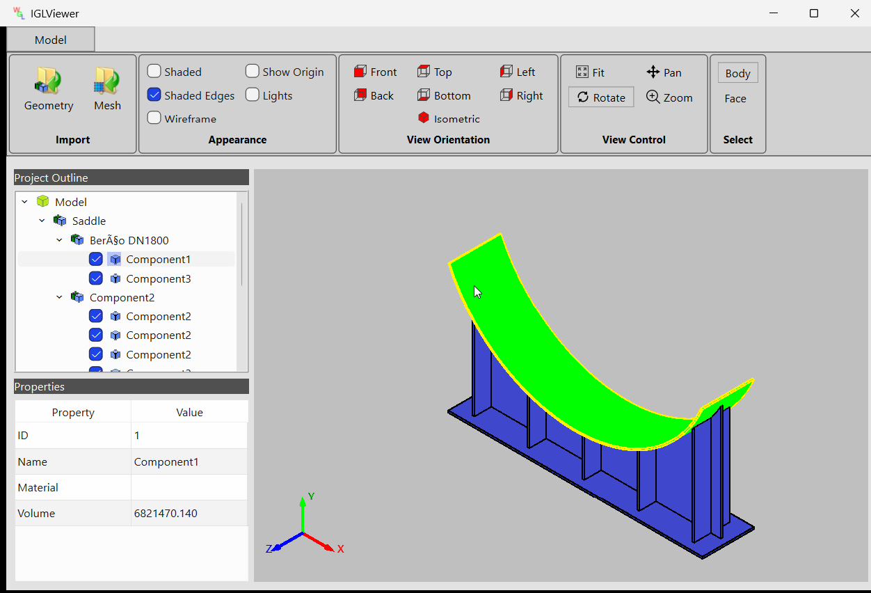
Core Features
CAD Import
Import STEP-based CAD assemblies converted into JSON geometry structures.
Mesh Visualization
Load and visualize finite element and polygon mesh data.
Interactive Camera
Orbit, pan and zoom using a custom OpenGL camera system.
Object Selection
Ray casting based body and face selection inside the 3D scene.
Graphical User Interface
The application interface is built using PySide6 and organized into multiple interactive panels.
Interactive Selection System
IGLViewer supports body and face level selection using ray casting. Mouse events from the OpenGL viewport are converted into 3D rays for accurate object intersection testing.
IGLViewer demonstrates how modern OpenGL, GPU rendering, PySide6 and custom visualization systems can be combined to create a professional engineering graphics application. It serves as a practical implementation of the concepts covered throughout this OpenGL tutorial series.
IGLGraphics combines PySide6, PyOpenGL and modern GPU rendering techniques to create a powerful platform for interactive engineering visualization. By understanding the complete OpenGL rendering pipeline, it becomes possible to build professional graphics applications capable of handling real-world CAD and scientific visualization problems.

Services
Industries
All rights reserved